
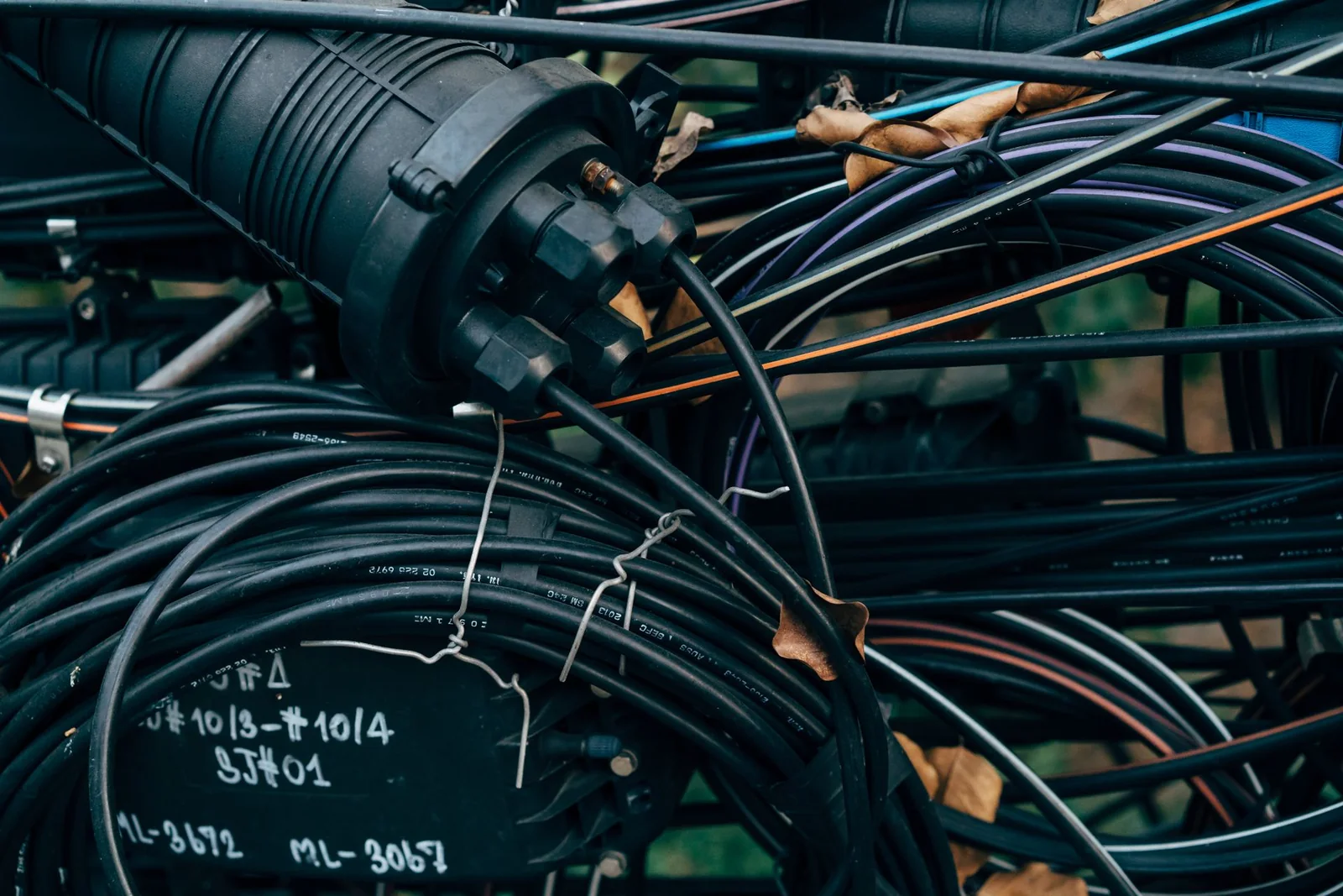
Protected fiber links are designed by understanding the route first. Armor, rugged jackets, conduit, and enclosures can reduce exposure to particular hazards, but no construction removes the need to control pulling, bending, crushing, water entry, connector handling, or future access. A useful procurement specification connects each environmental risk to a protective measure and then explains how the completed route will be inspected, tested, and maintained.
Build a route-specific risk map
Walk the proposed pathway before choosing cable construction. Divide it into sections with consistent conditions: indoor trays, equipment cabinets, outdoor ducts, exposed structures, underground pathways, and transition points. Record where the cable may encounter movement, vibration, moisture, debris, rodents, sharp edges, vehicle or foot traffic, or work by other trades. Site owners should also identify restricted areas and the practical windows for future maintenance.
Use a risk register rather than the word “rugged.” For every route section, record:
- Likely mechanical and environmental exposure
- Planned conduit, tray, support, or enclosure
- Pulling and placement method
- Minimum working space at transitions
- Location of splices, connectors, and slack storage
- Drainage, sealing, or fire-stopping responsibility where applicable
- Access method for inspection and repair
The record becomes the basis for comparing cable and hardware without assuming one protected assembly suits every section.
Match protection to installation and termination
Structural protection may be built into the cable or provided by the pathway around it. The correct combination depends on the surveyed hazards and installation method. Confirm the cable’s approved handling instructions with the manufacturer, including bend and pulling limits, permitted attachment method, and preparation requirements. Armor should never be treated as permission to kink the cable, pull through an unsuitable bend, or transfer load into a connector.
Plan how protection ends at cabinets, closures, or equipment. A transition that exposes fibers too early can undermine the protected route, while an inaccessible transition makes future repair difficult. The integrated fiber management tray can support organized routing and protected storage inside suitable termination hardware. In control cabinets, a DIN rail fiber terminal box offers a defined handoff between incoming fiber and connected equipment. Product fit still depends on cable entry, connector plan, available space, and site requirements.
Control bend, pull, and support during placement
Installation planning should state how the cable moves from delivery reel or coil to its final support. Inspect pathways for blocked ducts, damaged edges, tight turns, and congested entries before pulling begins. Use manufacturer-approved handling equipment and monitor the work so an unexpected obstruction is addressed rather than overcome with additional force.
Prepare a placement plan that identifies:
1. Cable feed and pull direction 2. Communication method between installation positions 3. Intermediate support and corner protection 4. Approved pulling attachment and lubricant, if relevant 5. Slack locations and temporary protection 6. Stop conditions for abnormal resistance or visible damage
After placement, secure the cable in a way that supports its weight without crushing it. Preserve service loops without creating uncontrolled coils, and keep protective caps on connectors until inspection and mating. Photographing concealed route stages can support the as-built record, provided each image is tied to a location and cable identity.
Design joints and access points for service
Splices, adapters, and removable connections need more protection and more access than uninterrupted cable sections. Locate them where technicians can work safely, control contamination, support the cable, and restore seals or covers after service. Do not bury a maintenance point behind unrelated equipment or place it where opening an enclosure disturbs neighboring links.
Label both the route and the individual fibers using identifiers that match drawings and test files. Document cable entry direction, stored slack, splice allocation, and connector polish type. The broader fiber network deployment plan should connect these details with termination, patching, and maintenance responsibilities. A protected route that cannot be identified or opened predictably remains difficult to operate.
Verify installation and preserve evidence
Acceptance should confirm physical condition, route completion, identification, enclosure integrity, connector cleanliness, and the optical results required by the project. Inspect accessible cable surfaces and every transition before covers are closed. Confirm that bend control, supports, slack, and seals match the approved installation plan.
For OTDR-based route checks, an OTDR launch cable can support a more usable launch setup. A visual fault locator may assist with tracing and obvious continuity issues during field work. Neither device defines acceptance on its own; the responsible engineering or quality document must state methods and limits.
Handover records should include the route drawing, cable identity, termination map, test files, exception log, photographs where useful, and instructions for accessing protected joints. Keep spare materials and replacement components identifiable. During maintenance, compare new observations with the baseline rather than treating each incident as an isolated fault.
A demanding route is successfully protected when hazards, construction, installation controls, and service access remain aligned. Protection is therefore a managed system of choices, not a single cable feature.
Discuss a related project