
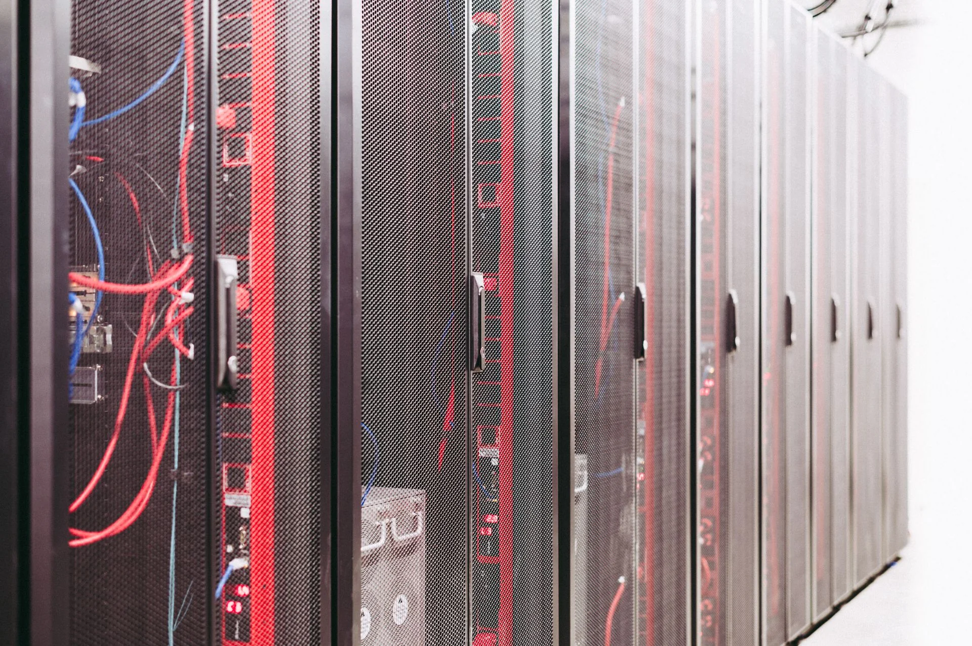
Network growth often appears first as a request for more fiber ports, but density is not simply a connector count. Every added path consumes routing space, label space, technician access, inspection time, and documentation capacity. A cabinet that can physically hold more adapters may still be difficult to operate if patch cords cover identifiers or prevent access to neighboring connectors. Planning fiber density therefore means designing an orderly service environment for present links and controlled expansion.
Measure usable cabinet space, not nominal capacity
Survey racks, wall boxes, control cabinets, and pathways with doors, covers, and neighboring equipment in their normal positions. Record where cables enter, where slack can be stored, how technicians reach connectors, and which areas must remain clear for airflow or electrical work. Include the space needed to open trays and use inspection tools. A port that cannot be safely reached is not useful capacity.
A density survey should document:
- Available rack units, cabinet depth, and door clearance
- Cable entry direction and pathway occupancy
- Adapter fields, splice areas, and slack-storage zones
- Working space for cleaning and inspection
- Separation from power, moving parts, and heat sources as required by site rules
- Current utilization and an approved expansion allowance
- Weight, support, and grounding requirements for installed hardware where applicable
A DIN rail fiber terminal box may support compact cabinet termination, while an integrated fiber management tray can help organize routing inside suitable distribution hardware. The correct choice depends on actual enclosure dimensions, cable entries, and service procedures.
Design routes that remain readable
High-density patching fails quickly when every cord takes the shortest visible path. Define horizontal and vertical routing zones, entry and exit directions, bend-control points, and destinations for excess length. Keep cords away from door hinges, fan trays, sharp edges, and controls. Route changes should be possible without pulling on adjacent connectors.
Use consistent patch-cord lengths selected from the measured path rather than collecting large loops near the adapter field. Where storage is necessary, keep it within approved management hardware and preserve access to labels. Separate permanent backbone or trunk connections from frequently changed service patching when the architecture allows. The aim is a layout technicians can understand before they touch it.
Document the routing convention in a simple cabinet diagram. Photographs can support that record, but they should supplement identifiers and drawings rather than replace them.
Make labels and records scale with port count
Dense infrastructure requires a naming system that remains unique across rooms, racks, panels, ports, cables, and fibers. The label printed at a connector should map directly to the design record and test result. Avoid codes that depend on local memory or change meaning when equipment is moved.
Before installation, test the proposed label format at full length on the smallest intended surface. Confirm that technicians can read it under normal cabinet lighting and distinguish both ends of similar cords. Maintain a controlled port schedule containing source, destination, service, fiber identity, connector type, status, and last authorized change. Reserve identifiers through the change process so temporary work does not create duplicate labels.
For moves, adds, and changes, require the record update as part of completion. An accurate empty-port inventory is as important as the occupied-port list because it guides expansion decisions.
Protect inspection and patching access
Connector density increases the chance that a technician will disturb a neighboring link while reaching the target interface. Provide room for safe removal, end-face inspection, cleaning, and remating. A handheld fiber end-face inspection system can support direct checks where access and adapter tips match the installed interfaces. For work across multiple locations, a portable end-face inspection kit may suit a transportable workflow.
Define an inspect-clean-inspect method and a way to protect disconnected services during work. Temporary caps, cord supports, and change labels should be ready before opening a dense panel. If a connector cannot be reached without removing unrelated cords, treat that as a layout issue and plan a controlled rearrangement rather than normalizing risky access.
Reserve growth without creating unmanaged clutter
Expansion planning should identify where the next hardware, cable entries, routing paths, and documentation records will go. Spare space is useful only when it is protected from unrelated use and reviewed against updated demand. Avoid filling every opening during the first build merely to advertise maximum density.
Use staged growth reviews:
1. Compare actual port use with the approved forecast. 2. Inspect pathway and management-space occupancy. 3. Check whether maintenance tasks remain practical. 4. Confirm spare identifiers, hardware, and patch-cord strategy. 5. Update cabinet drawings before the next installation stage. 6. Review power, cooling, and equipment constraints affected by active devices.
The data center and network deployment solutions provide a wider framework for coordinating density, cable organization, link planning, and service access.
Good density planning preserves options. It lets teams add connections without losing route clarity, inspection access, or record accuracy. The result is not the fullest cabinet; it is a cabinet that can grow while remaining understandable and maintainable.
Discuss a related project