
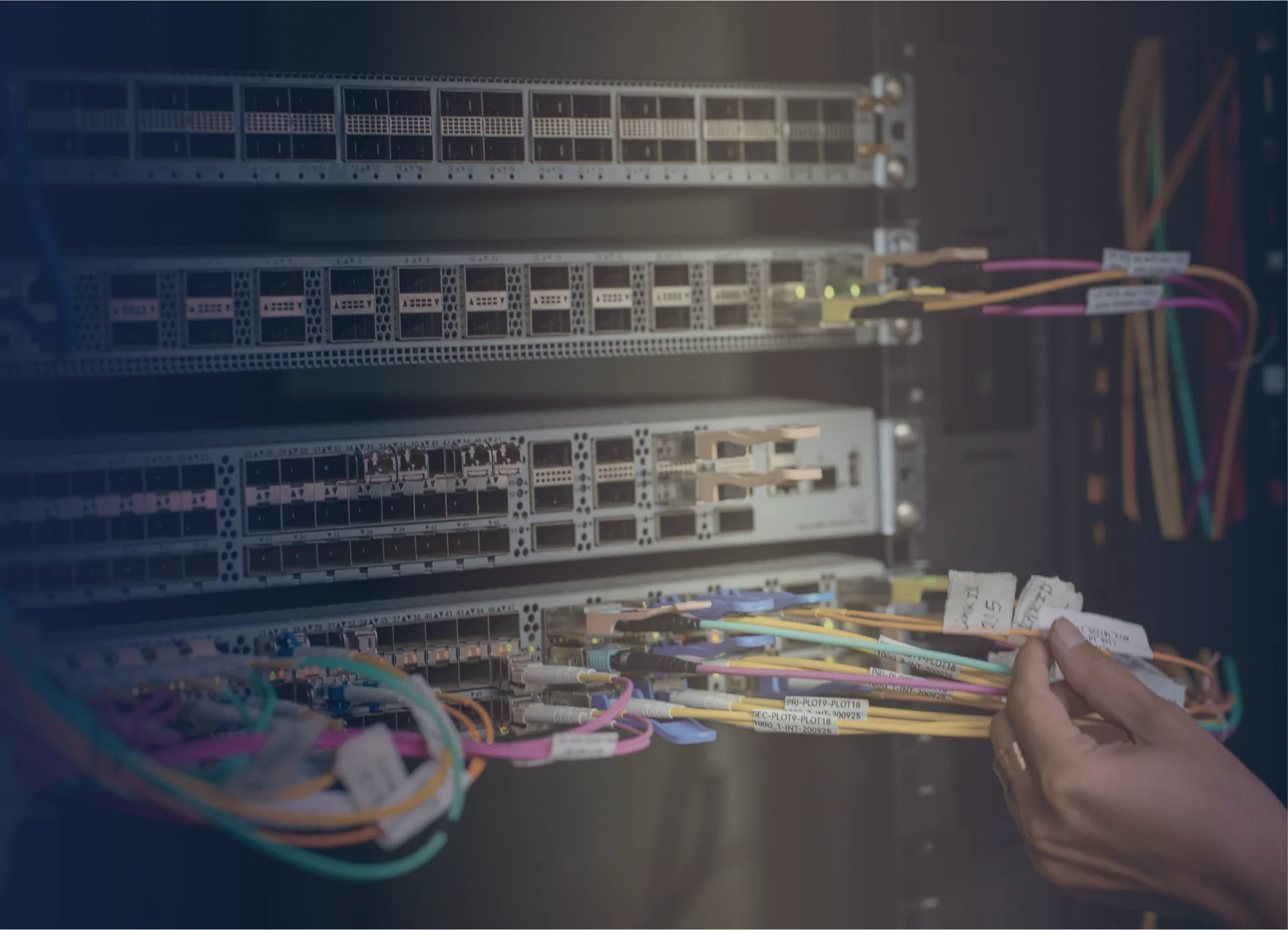
A reliable fiber installation is a controlled sequence from survey to handover. Problems often begin when one phase assumes another team has checked the route, material identity, connector condition, or records. A written checklist assigns those checks to clear moments and owners. It should reflect the approved project design and manufacturer instructions; it is not a replacement for engineering limits, site safety procedures, or customer acceptance criteria.
Survey and release the route
Confirm the physical pathway before materials are issued for installation. Walk both ends and every accessible intermediate section. Compare the observed route with drawings, note obstructions or changes, and verify that cabinets and closures can be reached in their final operating positions. Resolve pathway conflicts before cable pulling begins.
Survey checklist:
- Confirm endpoint names, cabinet positions, and cable entry locations.
- Check trays, ducts, conduits, penetrations, and support points.
- Identify bends, transitions, exposed areas, and shared pathways.
- Verify working access for pulling, termination, inspection, and future service.
- Record required sealing, fire-stopping, or environmental controls under site rules.
- Mark the approved route and escalation contact for deviations.
Do not accept an undocumented field shortcut simply because cable can pass through it. Update the route approval first.
Receive, identify, and stage materials
Match delivered cable, termination hardware, adapters, patch cords, and accessories to the approved bill of materials. Check packaging and visible condition before moving items into the work area. Keep product labels and reel or batch identities linked to the installation record where the project requires traceability.
Store cable and connectorized assemblies according to supplier instructions. Protect ends from contamination and physical damage. Separate accepted, suspect, and nonconforming material so technicians do not use an item while its status is unclear. Prepare labels before installation, but confirm final endpoint assignments before applying permanent identification.
For cabinet-based terminations, verify that a proposed DIN rail fiber terminal box fits the entry, routing, adapter, and service-access plan. An integrated fiber management tray should likewise be reviewed against the intended enclosure and fiber layout, not selected only by appearance.
Place cable under controlled conditions
Hold a pre-task briefing that covers feed direction, pull direction, communication, support locations, stop conditions, and responsibility for protecting other services. Inspect the pathway immediately before placement. Use handling methods and equipment approved for the selected cable, and follow its documented bend, pulling, and attachment limits.
During placement:
1. Protect cable at entries, corners, and temporary support points. 2. Keep connectors capped and supported if pre-terminated assemblies are used. 3. Watch for twisting, snagging, crushing, and abnormal resistance. 4. Stop and inspect rather than applying unplanned force. 5. Maintain separation and support required by the site design. 6. Leave controlled service slack only at documented locations. 7. Label both ends as soon as identity is confirmed.
Inspect the route before covers or access panels conceal the work. Record approved deviations on the as-built drawing.
Terminate, inspect, and clean interfaces
Prepare fibers and install connectors or splices using approved work instructions, tools, fixtures, and consumables. Keep the work surface organized so stripped material, cleaning waste, and finished interfaces do not mix. Protect completed fibers inside management hardware without tight bends or pressure from covers.
Every removable optical interface should enter an inspect-clean-inspect workflow. A portable fiber end-face inspection kit can support checks across field locations, subject to the connector tips and access needed by the project. Do not mate a connector merely because it has been cleaned; reinspection confirms whether the action produced an acceptable result under the governing procedure.
Record repairs or rework against the correct cable and fiber identity. If repeated cleaning or termination does not resolve a concern, isolate the part and escalate instead of continuing uncontrolled attempts.
Test the link and preserve source records
Testing must follow the approved method, direction, reference procedure, wavelengths, and limits supplied by the responsible project documentation. Inspect test leads and adapters before use. A visual fault locator can assist with tracing and obvious continuity issues, while an OTDR launch cable can support a documented OTDR setup. Neither tool alone proves that the installed link meets all acceptance requirements.
Name files so each result maps to the route, cable, fiber, direction, date, and test method. Preserve original instrument files when required, not only screenshots or transcribed values. Review exceptions before handover and make the disposition visible. If a link is retested after repair, retain both the repair record and the accepted final result according to project rules.
Hand over an installation that can be maintained
Close the project with a physical and documentary review. Confirm labels, panel schedules, stored slack, caps, enclosure covers, seals, and housekeeping. Demonstrate how technicians access termination points without disturbing adjacent fibers. Provide the approved as-built route, connection schedule, test package, exception log, product documentation, and maintenance instructions to the named owner.
Agree on future inspection points, spare-material ownership, and change-control method. The fiber network deployment solutions overview can help teams align termination, patch management, testing, and service access when planning later expansion.
A checklist succeeds when each item produces visible evidence or a clear decision. By keeping survey, receiving, placement, termination, inspection, testing, and handover connected, the team leaves behind a fiber link that others can understand and service safely.
Discuss a related project