
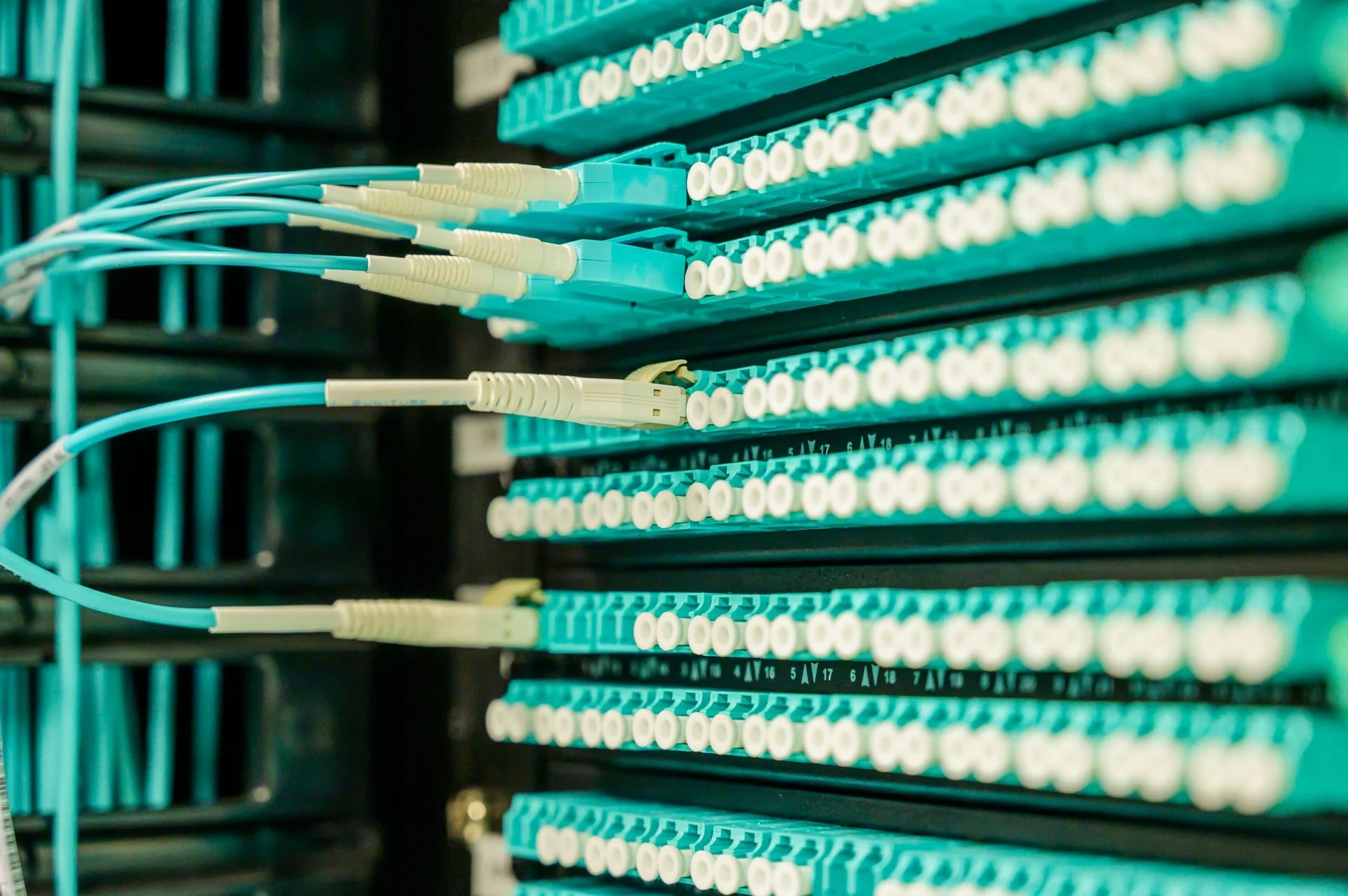
Fiber optic connectors are small parts with system-wide consequences. They create removable interfaces between cables, equipment, test leads, and distribution hardware, so a connector decision affects assembly work, field access, inspection, and later troubleshooting. Procurement teams should therefore review the connector as part of the complete optical link rather than as an isolated item. The useful questions concern compatibility, handling, verification, and the people who will maintain the connection after installation.
Begin with the link and service environment
Start by mapping every place where a removable connection is required. A factory-terminated assembly, equipment port, cabinet transition, and field service point may impose different constraints. Record the fiber type, connector family, equipment interface, cable construction, expected handling, and available working space. This map helps prevent a common purchasing error: selecting a familiar connector format before confirming how it will be installed and accessed.
A practical connector review should cover:
- Connector family and polish type at both sides of every mating point
- Cable and fiber construction entering the connector
- Adapter, transceiver, panel, or instrument interface
- Space for fingers, tools, cleaning, and inspection
- Identification method used during installation and service
- Expected frequency of connection, disconnection, or reconfiguration
For cabinet terminations, a DIN rail fiber terminal box can illustrate how termination, routing, and service access must be considered together.
Choose UPC or APC as a link decision
UPC and APC describe different end-face geometries. APC uses an angled physical-contact surface to direct reflected light differently from a non-angled physical-contact interface. The appropriate choice depends on the connected equipment, adapters, patching plan, and optical requirements defined by the system owner. Procurement should not substitute one polish type for another merely because the connector body appears similar.
Document the polish type in drawings, bills of materials, labels, work instructions, and test records. Confirm both ends of every adapter path and every test lead. Mixed or uncertain interfaces can create avoidable measurement questions and may damage end faces. If the network includes several connector families, make the approved combinations explicit instead of relying on color alone. Color conventions can help operators, but the controlled product identity should remain the primary reference.
Make end-face condition part of the process
A connector can be correctly specified and still perform poorly if its end face is contaminated, scratched, or handled incorrectly. Inspection should occur at defined points, especially before mating and after any cleaning action. The decision standard must come from the applicable project or quality procedure; a microscope image by itself does not determine acceptance.
The handheld fiber end-face inspection system supports direct review at a bench or field location, while the portable inspection kit is intended for work that benefits from a transportable set of inspection accessories. Equipment selection should follow the connector access map. Recessed ports, dense panels, and patch-cord ends may require different tips, holders, or working positions.
Use an inspect-clean-inspect sequence. Protect a verified connector until it is mated, and keep caps, adapters, and cleaning tools under the same handling discipline. Cleaning without reinspection leaves the result unknown.
Control mating, polishing, and optical verification
Connector quality is created across several linked steps. Ferrule preparation and polishing establish the finished surface; inspection checks visible condition; optical testing evaluates the completed assembly within the defined test method. Teams producing connectorized assemblies can review a fiber optic polishing machine as one element of that workflow, not as a substitute for fixtures, consumables, cleaning, or inspection.
Before release, verify that mating adapters and test leads match the connector and polish type. Define how reference connections are prepared, when test accessories are inspected, and how unexpected readings are investigated. An insertion and return loss tester can support production verification, but acceptance limits and reference procedures must come from approved project documentation. Records should identify the assembly, test direction where relevant, operator or station, and disposition of any exception.
Plan for the connector lifecycle
The connection remains part of the system long after initial acceptance. Service teams need enough slack, routing control, labeling, and physical access to inspect or replace an assembly without disturbing neighboring fibers. Procurement should ask how spare adapters, inspection tips, cleaning materials, and compatible patch cords will be identified and stored. Documentation should show the actual installed mating path, not only the original purchase description.
During design review, walk through one future maintenance event. Identify which panel will open, which cable can move, how the connector will be inspected, and how the restored link will be checked. The broader fiber network deployment approach can help teams connect product selection with routing, test, and service planning.
A sound connector choice is therefore one that remains compatible, inspectable, and maintainable throughout the link lifecycle. That outcome comes from a controlled interface plan and repeatable handling—not from choosing a connector name in isolation.
Discuss a related project